Automatic Water Level Controller for Pump using 555 Timer IC Hackster.io
The circuit will automatically switch ON any water pump / motor when the level of water in a tank reaches below from the required level and automatically switch OFF the pump after filling the tank. Here is a very useful project of an automatic water pump controller circuit.
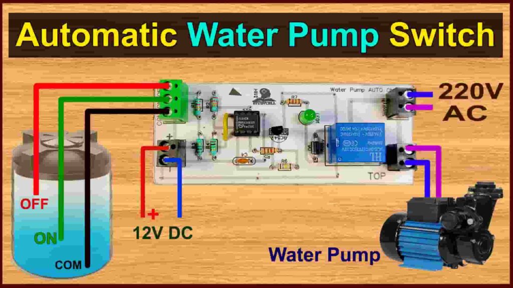
Automatic Water Pump Switch ONOFF Circuit with 555 Timer
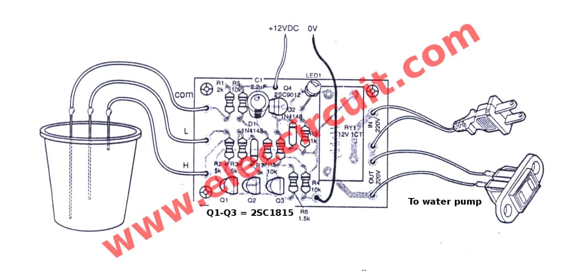
The article describes a simple low cost automatic water pump controller circuit. The circuit measures water levels in the tank with the three probes, and automatically switches ON the pump on the desired low level of water and automatically switch it OFF on the desired high level of water. Hello Readers, We frequently add new circuit diagrams.
5 Automatic Water Level Controller Circuits
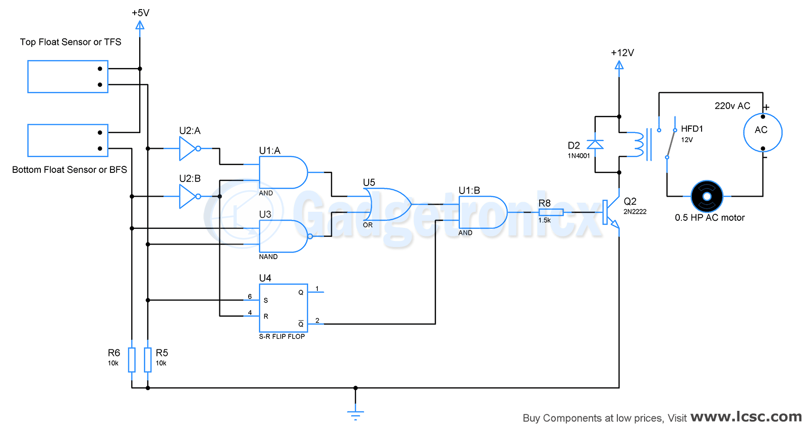
What it does? The circuit automatically turns on and off the pump that fills the tank by monitoring the level of water inside it. After reaching the upper threshold the pump turns off and after going below a lower threshold the pump turns on. The wireless control cuts the cost of wire that needs to be connected from the tank to the pump circuitry.
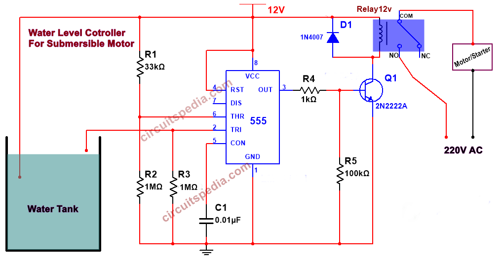
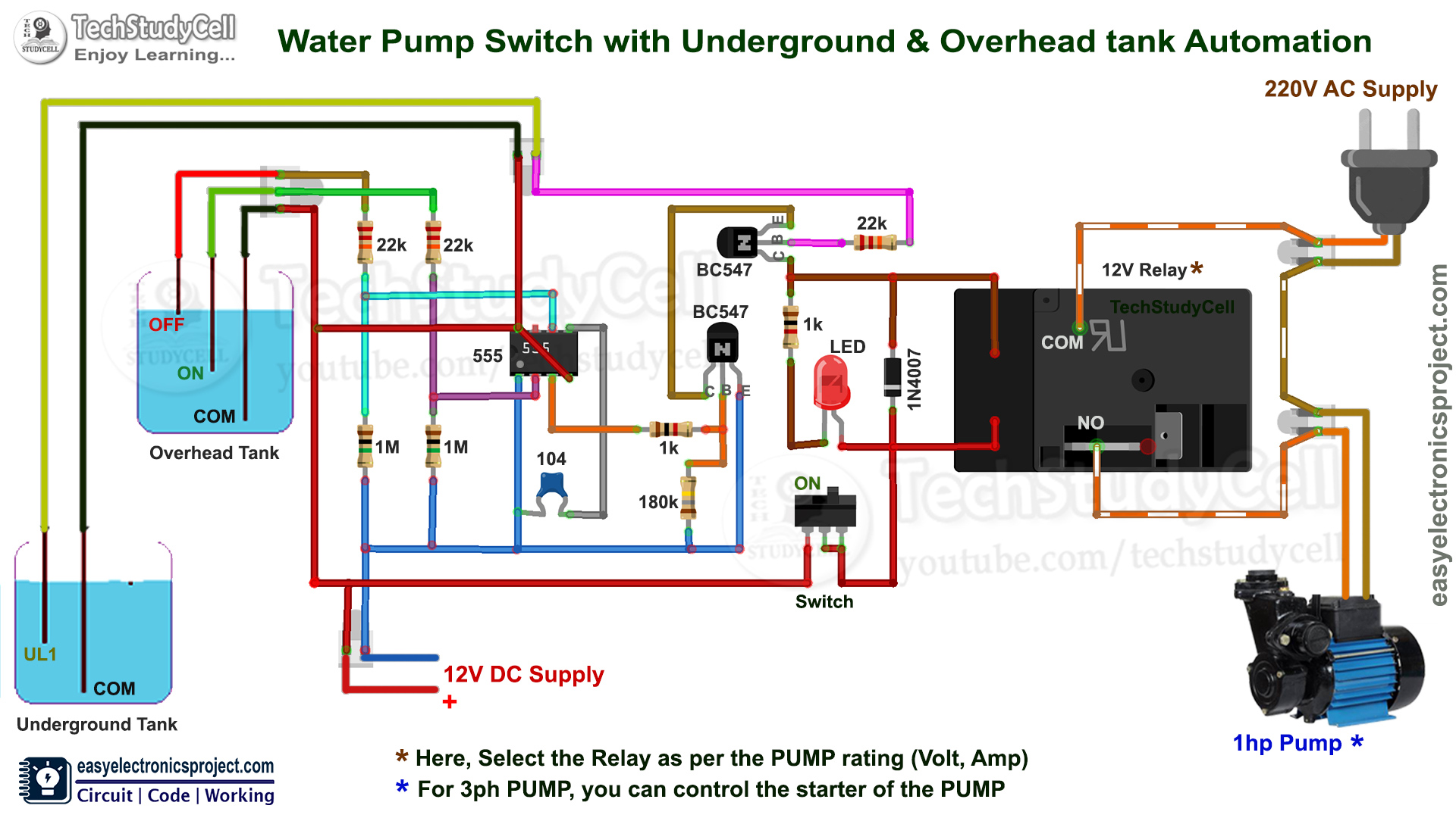
Automatic Water Pump Controller Circuit for submersible motor using 555
Try the eBay way-getting what you want doesn't have to be a splurge. Browse Waterer pump control! No matter what you love, you'll find it here. Search Waterer pump control and more.
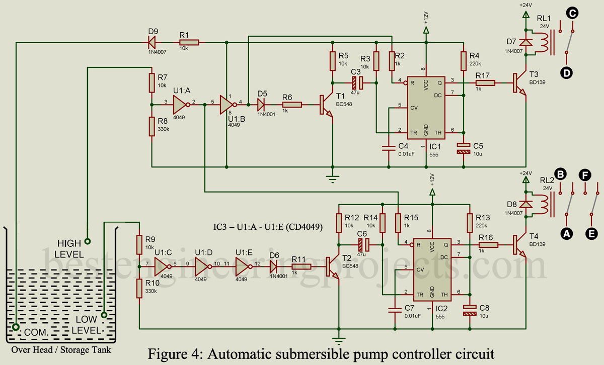
Automatic Submersible Pump Controller Circuit Engineering Projects
The VF water pump controller is designed based on the TMS320F2802XTM microcontroller (MCU) with sensorless technology, which can implement constant speed and power controls. The VF water pump has several advantages over a traditional water pump. Energy savings: Achieve a remarkably high efficiency at a low rpm with variable frequency control.
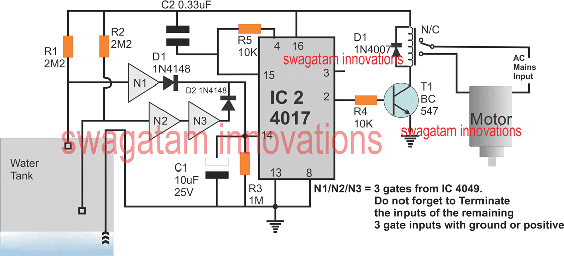
Control Two Submersible Pumps Alternately Homemade Circuit Projects
The automatic water pump controller using Arduino is a project that aims to automate the control of water pumps based on specific conditions or requirements. It utilizes the Arduino microcontroller board, along with various sensors and components, to monitor the water level and control the operation of the water pump accordingly.
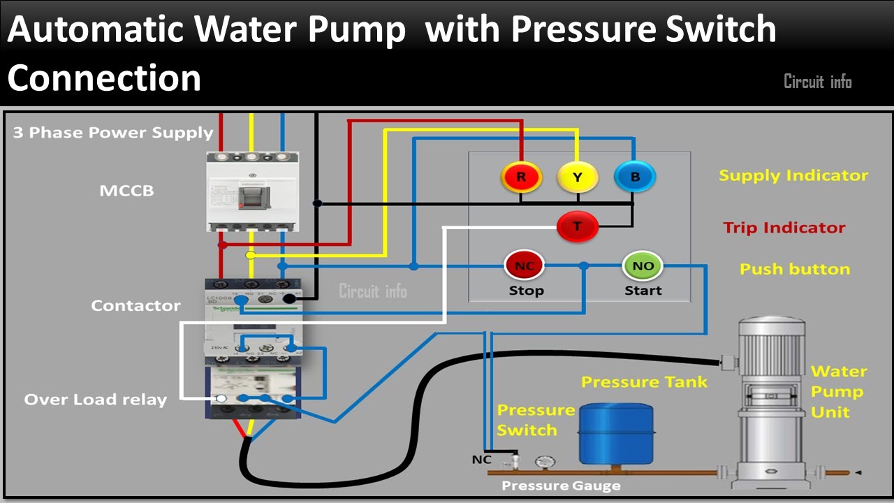
Water Pump Switch Wiring Schematics
An automatic water pump controller for a submersible pump is a convenient and efficient solution for maintaining the water level in a tank or reservoir. This 555 IC circuit ensures that the pump operates only when the water level falls below a certain point, preventing dry running and water overflow.
Automatic Water Level Controller for Pump using 555 Timer IC Hackster.io
Step 1: Connect the Motor to the MOSFET Step 2: Connect the Ground Pin Step 3: Connect the MOSFET's gate pin Step 4: Connect the resistor between Gate and the ground Step 5: Connect the diode across the motor cable Step 6: Verify the complete connections Arduino Code Example For The Arduino And The Water Pump Project Project 1: Motor ON OFF Code
Single Phase Jet Pump Controller Circuit Homemade Circuit Projects
Explanation of circuit: The ultrasonic sensor is connected to digital input pins of Arduino. Arduino shows the status of motor and water level on the 16 x 2 LCD. If the water level decrease to below 100 centimeters, the motor turns ON. When the level of water becomes more than 40 centimeters microcontroller automatically turns OFF the motor.

Circuit diagram of water pump control system Download Scientific Diagram
How to Make Fully Automatic Water Pump Controller | Water Level Indicator and Pump ControllerIn this video, you will learn how to make a water pump controlle.
Automatic water level controller 2 circuits choice
The article portrays a basic and economical "automatic water pump controller" circuit. A "water pump controller" detects the level of water in a tank and drives the water pump. The controller controls the output and speed of the pump. The input factors are given by different sensors, for example, level sensors and flow meters. At that.
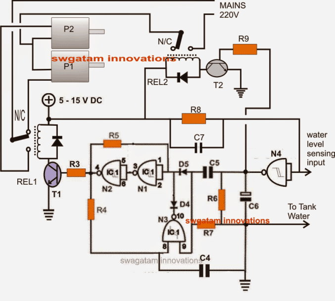
Low Cost Water Pump Controller circuit Todays Circuits Engineering Projects
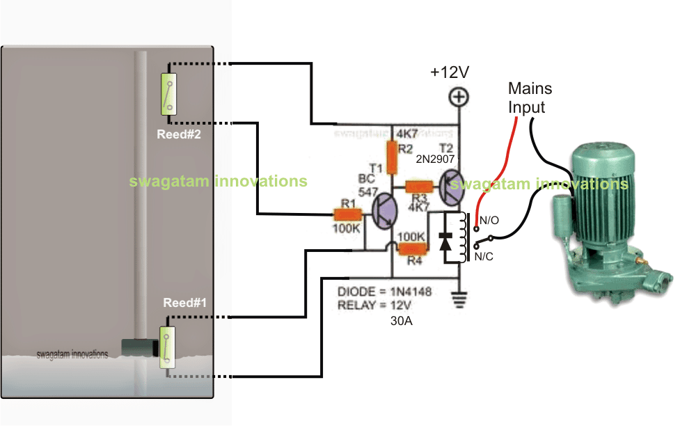
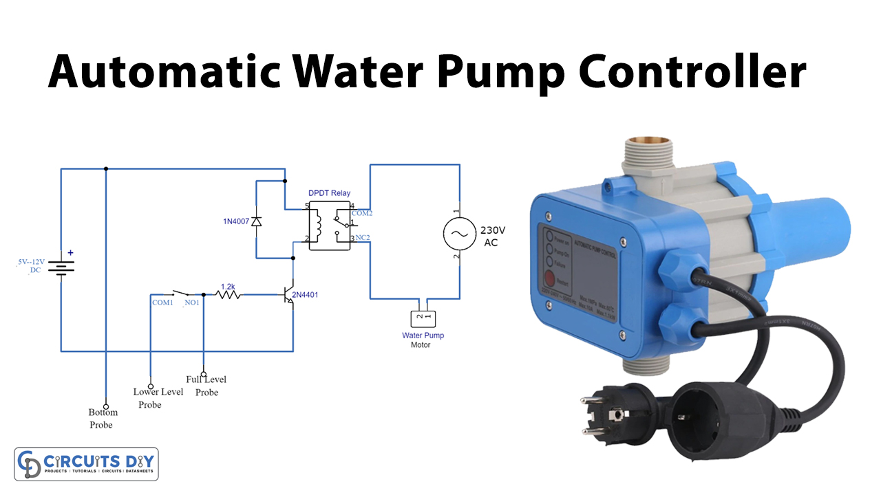
Circuit Operation. In this section, we talk about the circuit operation of an "automatic water pump controller". The circuit is utilizing just three segments which are a 2N4401 transistor, one 1.2K resistor, and one DPDT relay. There are three probes in the circuit which ought to be set in the water, and any thin wire will carry out the job.
Automatic water pump controller Gadgetronicx
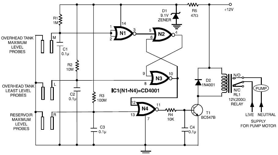
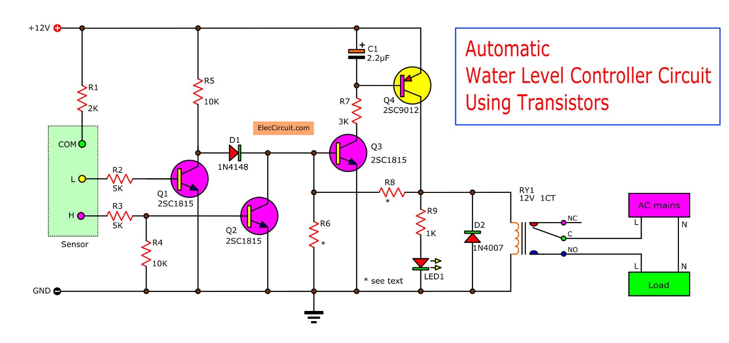
A water pump controller senses the level of water in a tank and drives the water pump. The circuit described here is built around timer IC1 (555). When the water level of the tank goes below the low level marked by 'L' the voltage at pin 2 of IC1 becomes low. As a result, internal SR- flip-flop of IC1 resets and its output goes high.
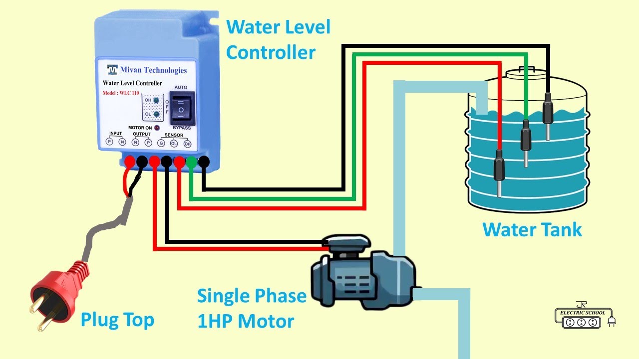
Automatic Control For Water Pump Wiring Diagram Wiring Diagram
Automatic Water Pump Controller Circuit Working Explanation The operating voltage of this circuit is 9 to 12 volts DC. This circuit is built around the timer IC NE555. When the water will be below the bottom level probes the IC will be activated and turns the relay on, which will turn on the pump.
Automatic water level controller circuit project
The purpose of this circuit is to control any liquid or water pump according to the desired upper and lower level of the container or tank. This circuit is completely automatic. There are three sensor points specified for each level marked as A, B, and C as shown in the circuit diagram, they will be placed at different levels in the water tank.
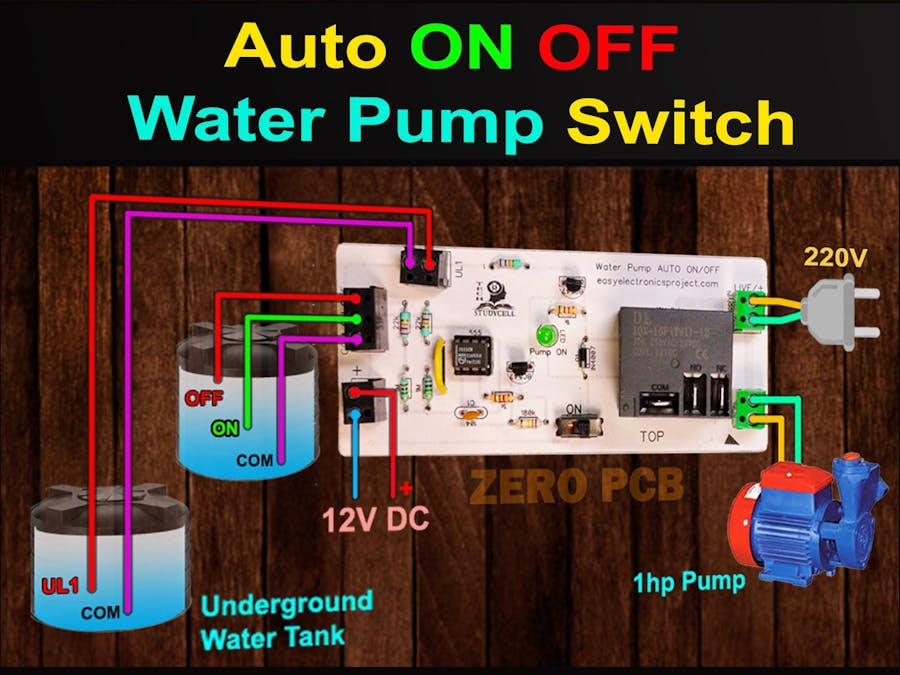
Automatic water pump on off water level controller YouTube
Circuit Operation If the tank is filled below probe A, transistors T1 and T2 do not conduct and the output of N3 goes high. This high output energizes relay RL2 to drive the motor and it starts pumping water into the tank.