
[DIAGRAM] Wiring Diagram Panel Ats Genset
A wiring diagram ATS Genset is one of the most important elements of a power system. It provides a visual representation of the electrical connections within a power plant, ensuring that all components are appropriately wired and that everything is functioning properly. Wiring diagrams are essential for troubleshooting, repair, and maintenance of power systems.
RANGKAIAN PANEL ATS AMF GENSET
Automatic mains failure (AMF) panels, often referred to as automatic transfer switch (ATS) panels, make the power switch to emergency standby generators in the event of a significant loss of mains power or total blackout.
️Wiring Diagram Ats Amf Genset Free Download Goodimg.co
3 - Working Principle of AMF panel: When the AMF panel senses that mains has failed then it provides a start signal to the DG. After starting the DG, the breaker is connected to the load. This all activity has been done in automatically. When backup supply is detected then AMF panel sends a tripping signal to the DG breaker after tripping DG.
Wiring Diagram Ats Amf Genset Upblog
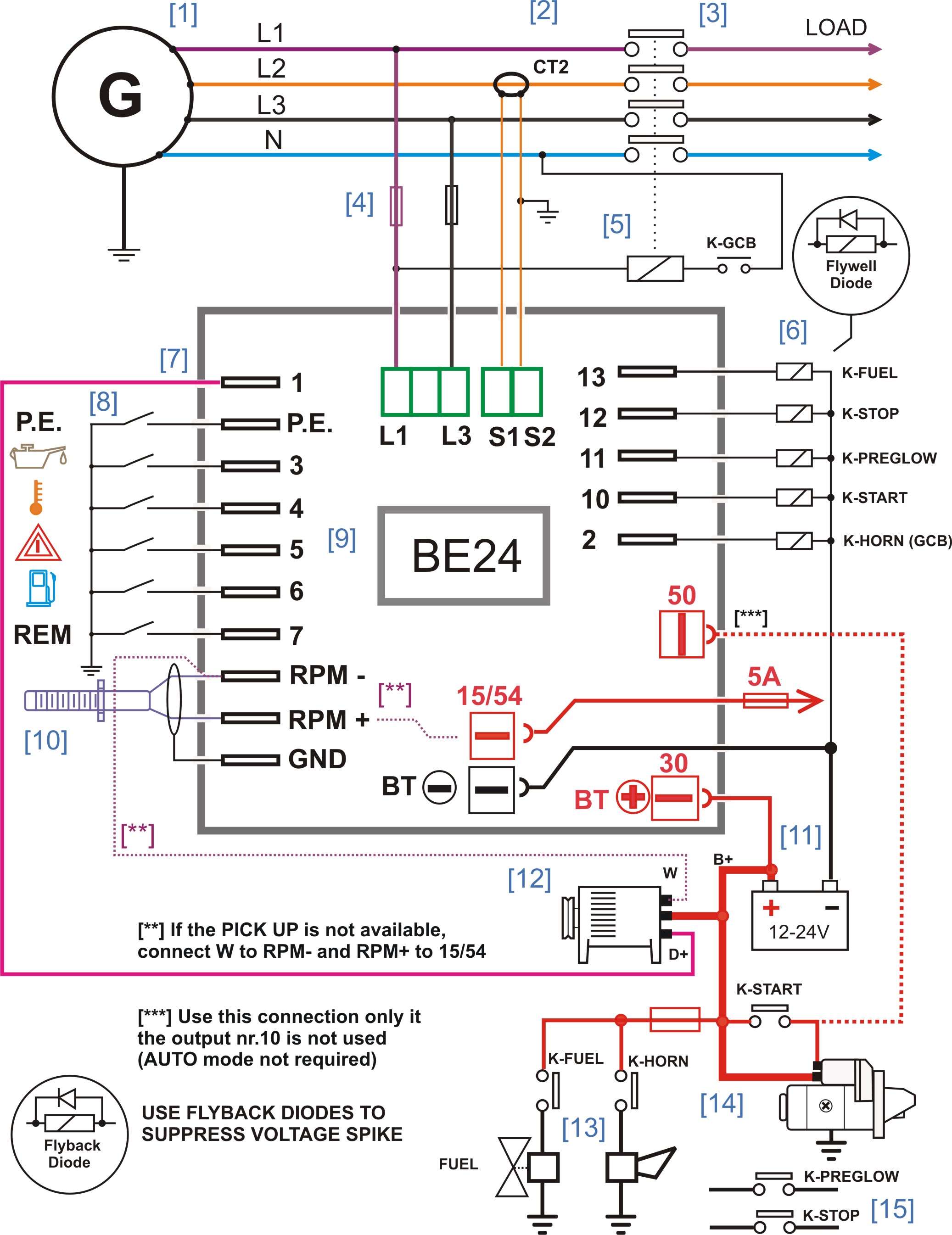
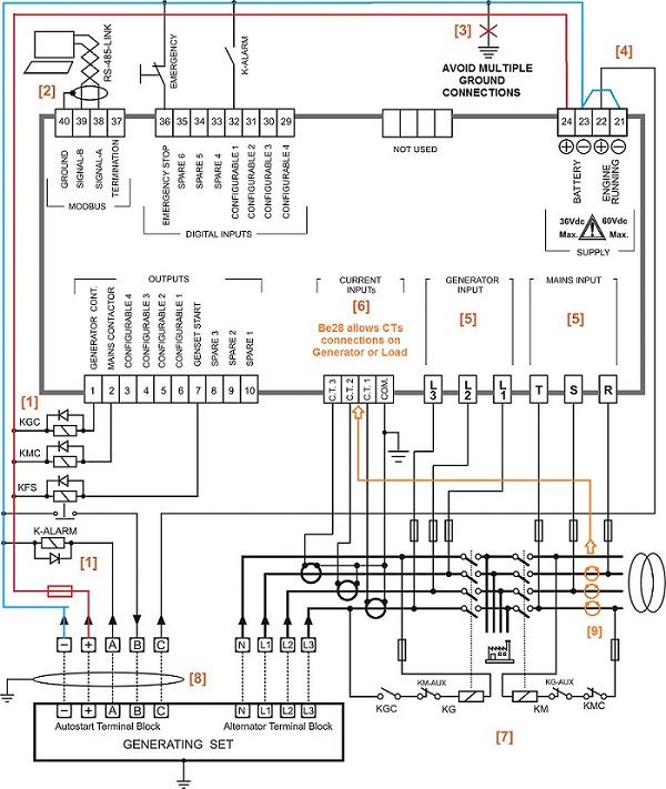
This AMF panel wiring diagram illustrates the connections of the BeK3-ZERO AMF controller. It monitors the parameters of the mains automatically start the engine via relays or interface board. Once the generator provides the correct frequency and voltage, the controller transfers the load from the mains to the generator.
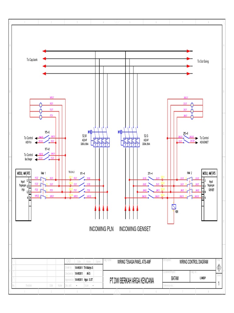
Wiring Tenaga Panel AtsAmf
#Emko Trans-AMF Automatic Genset Controller with Transfer Switch wiring pdf diagram explain #wiring #Emkopdf #Wiring #generatorwiringTrans-AMF - Automatic Ge.
Wiring Diagram Ats Genset Wiring Digital and Schematic
Understanding Wiring Diagrams ATS AMF Wiring diagrams ATS AMF are essential for any electrical or engineering design project. These diagrams provide detailed information on the wiring systems of electrical components, and can be used to help assess and troubleshoot any problems that may arise. Wiring diagrams ATS AMF are typically used by electricians, engineers, and technicians to ensure.

wiring diagrams ats generator
0:00 / 18:02 Wiring Diagram Panel ATS / AMF Genset NickNo Techno 4.98K subscribers 10K views 3 years ago Panel ATS AMF.more.more Wiring Panel Listrik ATS (Automatic Transfer.
Wiring Diagram Panel Ats Genset Home Wiring Diagram
Dec 27, 2013. #7. GoldDigger said: Even if insulated to the same voltage, the control wiring has to be functionally related to the power wiring to be in the same raceway. One AHJ was reported to not even consider the remote start and voltage monitoring wires for a generator to be functionally related to the generator output.
ATS, Automatic Transfer Switch, ATS Control Panel Wiring Diagram YouTube
INTRODUCTION. The AMF-10 is one control with two jobs, one is to protect and control the emergency generator and the other is to monitor and control the Automatic Transfer Switch. The customer can program the AMF-10 module directly from the front panel without using a computer.

Generator Ats Wiring Diagram
Wiring diagrams of ATS/AMF systems typically include a schematic drawing of the power flow and the components used, along with an arrangement of the various components and wiring runs. As with any electrical system, it's important to ensure all connections are correctly identified and labeled. Additionally, the wiring diagram should include.
Wiring Diagrams For Ats To Generator
#sumberteknik #seputargenset #panelamfatsWIRING PANEL AMF-ATS COS MOTORIZEDWIRING DIAGRAM SOCOMEC AtySLink Download file pdf:https://drive.google.com/uc?expo.
Wiring Diagram Kunci Kontak Genset Wiring Diagram and Schematics
The Crucial Role of Wiring Diagrams in ATS and AMF Systems: 1. Seamless Power Transitions: ATS systems are designed to automatically switch between the primary power source (often the grid) and a secondary power source (typically a generator) during power outages. Wiring diagrams are instrumental in understanding how this transition occurs.
ATS Control Panel Standby Generator genset controller
The wiring diagram panel Ats Amf provides a visual representation of the components and their connections. By studying the symbols and labels on the diagram, one can understand the flow of electricity and how the components are connected. With a better understanding of the wiring diagram, one can more easily troubleshoot any issues that may arise.

Wiring Diagram Panel Kontrol Genset Wiring Digital and Schematic
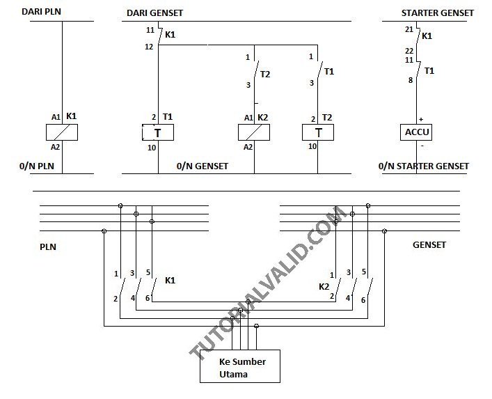
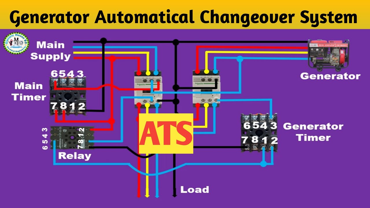
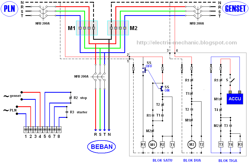
Berikut ini merupakan gambar wiring diagram daya dan kontrol sistem ATS (Automatic Transfer Switch) AMF (Automatic Main Failure) yang bisa kalian pasang pada panel listrik. Rangkaian Kontrol sistem ATS /AMF Gambar di atas merupakan rangakain atau wiring diagram kontrol sistem ATS AMF.

Wiring Diagram Ats Amf Genset
Following the wiring diagram, the electrician will mount the ATS, connect the main load breakers, and connect the load circuits. By following these steps, you can ensure that your ATS genset panel is correctly installed and that your critical loads remain powered even during an outage. Petunjuk Panel Ats Amf Pln Genset Otomatis Onematics
RANGKAIAN PANEL ATS AMF GENSET
Wiring diagrams are used to show how the various components of an ATS Genset are connected. In this article, we will discuss the basics of ATS Genset wiring diagrams and how they can be used to ensure your ATS Genset is operating safely and efficiently. Overview of Wiring Diagrams for ATS Gensets